1. Giriş
This manual provides detailed instructions for the Valefod 1-Channel 5V Relay Module. This module is designed to control various AC/DC appliances and other devices requiring high current switching, utilizing a genuine high-quality 5V relay and SMD opto-isolator for high/low level triggering. It is compatible with a wide range of microcontrollers.
Temel Özellikler:
- Kontrol araçları: Utilizes a DC5V relay and SMD opto-isolator for high/low level trigger, suitable for controlling AC/DC appliances and high-current devices.
- Yük aralığı: Normally Open (NO) maximum load: AC 250V/10A, DC 30V/10A. Opto-isolator trigger current: 5mA.
- Fault-tolerant Design: The relay remains inactive even if the control line is disconnected, enhancing safety.
- Evrensel Arayüz: Features screwed terminal plates and fixed bolt holes (3.1 mm diameter) for easy installation.
- Yüksek Uyumluluk: Directly controllable by 5V logic signals from microcontrollers such as 8051, AVR, PIC, DSP, ARM, Raspberry Pi, and MSP430 (TTL logic compatible).
2. Ürün Bittiview
The Valefod 1-Channel 5V Relay Module is a compact and versatile component for electronic projects. Below are images illustrating the module and its key components.

Şekil 2.1: Yukarıdan aşağıya view of the Valefod 1-Channel 5V Relay Module. This image displays the module from above, highlighting the 5V relay, screw terminals for input (DC+, DC-, IN) and output (NO, COM, NC), and the high/low level trigger selection jumper.

Figure 2.2: Valefod 1-Channel 5V Relay Module with Dimensions. This image shows the physical dimensions of the module, measuring 51mm in length, 26mm in width, and 19mm in height.
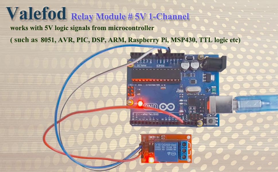
Figure 2.3: Relay Module Connected to a Microcontroller. This image illustrates the relay module connected to an Arduino board, demonstrating its compatibility with 5V logic signals from microcontrollers.
3. Özellikler
| Şartname | Değer |
|---|---|
| Röle türü | 5V 1-Channel |
| Kontrol Devresi | TTL gate circuit |
| Durgun Akım | 5mA |
| Maksimum Akım | 190mA |
| Tetikleme Akımı | 3 - 5mA |
| Tetik Hacmitage (LOW) | 0 - 1.5V |
| Tetik Hacmitage (HIGH) | 2.5 - 5V |
| NO Maximum Load | AC 250V, 10A or DC 30V, 10A |
| Güç Göstergesi | Yeşil LED |
| Röle Durum Göstergesi | Kırmızı LED |
| Boyutlar (U x G x Y) | 51mm x 26mm x 19mm |
| Ağırlık | 17 gr |
| Bağlayıcı Türü | Vidalı terminal |
| İletişim Malzemesi | Gümüş Alaşım |
| İletişim Türü | Normally Closed (NC), Normally Open (NO) |
| Montaj Tipi | Vida Bağlantısı |
4. Kurulum Talimatları
Proper setup is crucial for the safe and effective operation of the relay module. Follow these steps for connection and configuration.
4.1. High/Low Level Trigger Selection
The module supports both high-level and low-level triggering. This is selected using a jumper cap on the module:
- High Level Trigger: Connect the jumper wire to the 'High' pin. The relay will activate when the input signal (IN) is high (2.5V - 5V).
- Low Level Trigger: Connect the jumper wire to the 'Low' pin. The relay will activate when the input signal (IN) is low (0V - 1.5V).
4.2. Input Interface Connections
The input side of the module connects to your power supply and control signal:
- DC+: Connect to the positive pole of your 5V power supply (VCC).
- DC-: Connect to the negative pole of your power supply (GND).
- İÇİNDE: Connect to the control signal from your microcontroller or other logic source. This pin triggers the relay based on the selected high/low level setting.
4.3. Output Interface Connections
The output side of the module connects to the device you wish to control. The relay acts as a switch for the load circuit:
- HAYIR (Normalde Açık): This terminal is disconnected from COM when the relay is inactive. It connects to COM when the relay is activated (pickup).
- COM (Ortak): This is the common terminal of the relay switch.
- NC (Normalde Kapalı): This terminal is connected to COM when the relay is inactive. It disconnects from COM when the relay is activated (pickup).
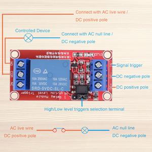
Figure 4.1: Basic Wiring Diagram for AC/DC Load. This diagram illustrates how to connect the relay module to control an AC or DC powered device. The signal trigger, DC positive, and DC negative poles are shown on the input side, while the controlled device connects to the output terminals (NO, COM, NC).
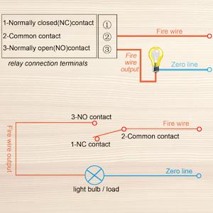
Figure 4.2: Relay Contact States. This diagram clarifies the functionality of the NO, COM, and NC terminals, showing how they connect or disconnect based on the relay's activation state, using a light bulb as an exampyük.
5. Kullanım Talimatları
Once the module is correctly wired, its operation is straightforward, controlled by the input signal from your microcontroller.
5.1. Controlling the Relay
The relay module is designed to be controlled by 5V logic signals. When the 'IN' pin receives the appropriate trigger signal (high or low, depending on your jumper setting), the relay will activate. This action switches the connection between the COM terminal and either the NO or NC terminal.
- If configured for High Level Trigger, applying a voltage of 2.5V to 5V to the 'IN' pin will activate the relay.
- If configured for Low Level Trigger, applying a voltage of 0V to 1.5V to the 'IN' pin will activate the relay.
The red LED on the module indicates the relay's status: it illuminates when the relay is activated.
5.2. Microcontroller Integration
The module is highly compatible with popular microcontrollers. Connect the microcontroller's 5V output to DC+, GND to DC-, and a digital output pin to the 'IN' pin. Program your microcontroller to send the desired high or low signal to control the relay.
6. Bakım
The Valefod 1-Channel 5V Relay Module is designed for durability and requires minimal maintenance. Adhering to these guidelines will help ensure its longevity and reliable performance.
- Temiz tut: Ensure the module is free from dust, dirt, and moisture. Use a soft, dry cloth for cleaning.
- Çevresel Koşullar: Operate the module within its specified temperature and humidity ranges. Avoid extreme heat, cold, or high humidity environments.
- Güvenli Bağlantılar: Periodically check all screw terminal connections to ensure they are tight and secure. Loose connections can lead to intermittent operation or overheating.
- Aşırı Yüklemeden Kaçının: Do not exceed the maximum load ratings (AC 250V/10A, DC 30V/10A) for the relay contacts. Overloading can damage the relay and connected devices.
7. Sorun Giderme
If you encounter issues with your Valefod 1-Channel 5V Relay Module, refer to the following troubleshooting tips.
- Röle Aktif Değil:
- Verify the 5V power supply is correctly connected to DC+ and DC-. The green power LED should be on.
- Check the 'IN' signal. Ensure your microcontroller is sending the correct voltage level (high or low) as per the jumper setting.
- Confirm the high/low level trigger jumper is correctly positioned.
- Ensure the control line to 'IN' is not disconnected, as the fault-tolerant design prevents activation in this state.
- Yük Değiştirilmiyor:
- Check if the red relay status LED illuminates when the 'IN' signal is applied. If not, troubleshoot relay activation first.
- Verify the load wiring to the NO, COM, and NC terminals. Ensure the load is connected to the appropriate terminals for your desired operation (e.g., COM and NO for normally off, COM and NC for normally on).
- Confirm the load's power supply is active and correctly connected.
- Ensure the load's current and voltage requirements do not exceed the relay's maximum ratings (AC 250V/10A, DC 30V/10A).
- Aralıklı operasyon:
- Inspect all wiring for loose connections, especially at the screw terminals.
- Check for power supply fluctuations or noise affecting the control signal.
8. Garanti ve Destek
Valefod products are manufactured to high-quality standards. For specific warranty information, please refer to the product packaging or contact your retailer. For technical support or further assistance, please reach out to Valefod customer service through the official channels provided at the point of purchase or on the Valefod webalan.


