1. Giriş
This manual provides comprehensive instructions for the installation, operation, and maintenance of the Supermicro X10SLM+-LN4F motherboard. Designed for server applications, this motherboard features an LGA1150 socket, Intel C224 PCH, DDR3 memory support, and multiple Gigabit Ethernet ports. Please read this manual thoroughly before proceeding with installation to ensure proper setup and optimal performance.
2. Ürün Bittiview
The Supermicro X10SLM+-LN4F is a microATX server motherboard built for reliability and performance. Key features include:
- LGA1150 Socket for Intel Xeon E3-1200 v3/v4 and 4th Gen Core i3 processors.
- Intel C224 PCH chipset.
- Four DDR3 DIMM slots supporting up to 64GB ECC/non-ECC UDIMM.
- Multiple SATA3 (6Gbps) ports.
- Integrated quad Gigabit Ethernet ports.
- USB 3.0 and USB 2.0 support.
- VGA output for integrated graphics.
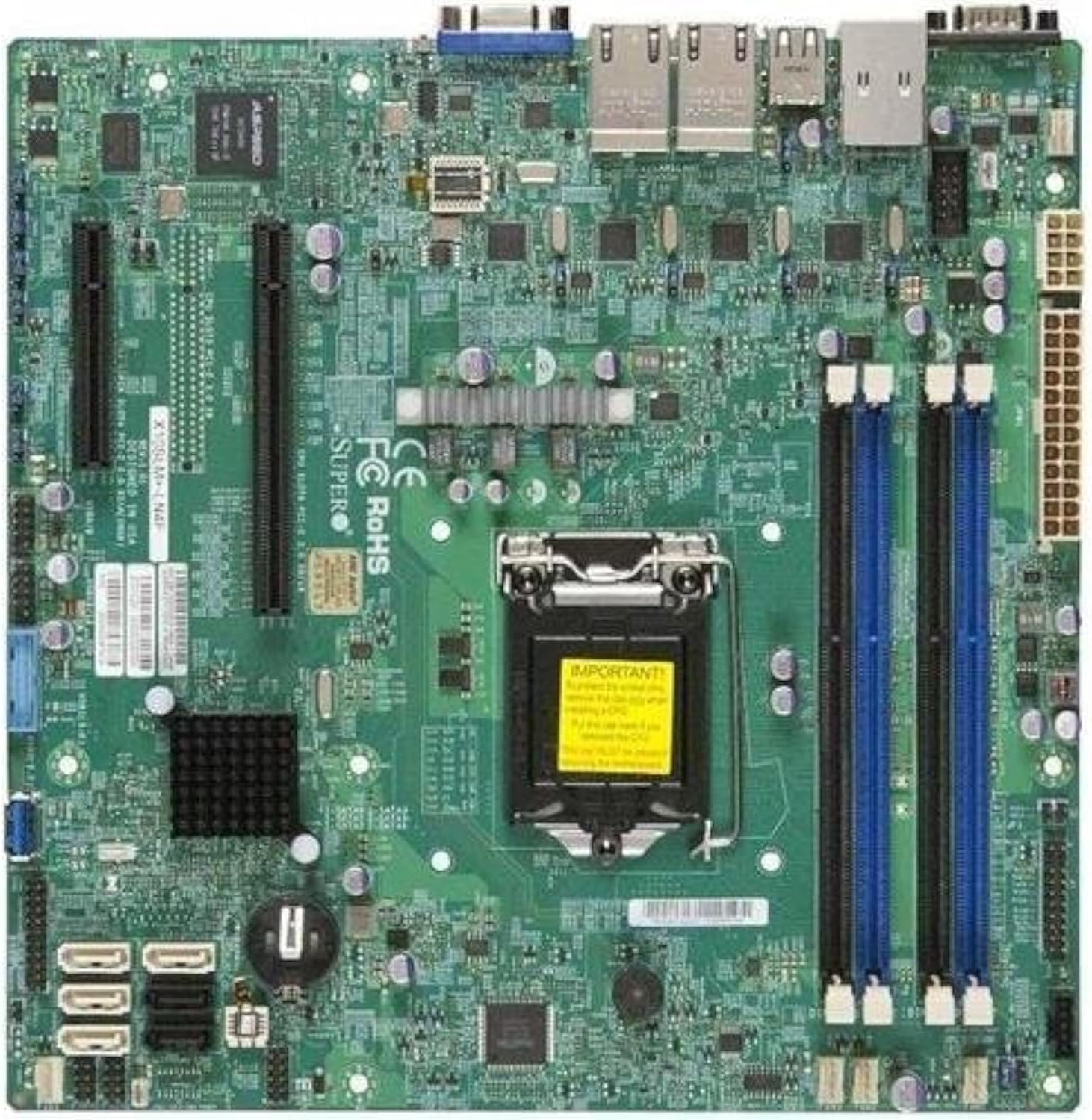
Şekil 2.1: Yukarıdan aşağıya view of the Supermicro X10SLM+-LN4F motherboard, showing the CPU socket, DIMM slots, PCIe slots, and various connectors.

Şekil 2.2: Açılı view of the motherboard, highlighting the layout of components and expansion slots.
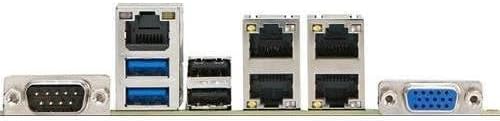
Şekil 2.3: Rear I/O panel of the Supermicro X10SLM+-LN4F motherboard, featuring multiple LAN ports, USB ports, and serial ports.
3. Kurulum ve Kurulum
Before beginning installation, ensure your system is powered off and disconnected from the power source. Wear an anti-static wrist strap to prevent electrostatic discharge (ESD) damage to components.
3.1. CPU Kurulumu
- Anakart üzerinde LGA1150 CPU soketini bulun.
- Yükleme kolunu yavaşça aşağı itin ve CPU soketi tutma çerçevesini açmak için yana doğru çekin.
- CPU üzerindeki üçgen işaretini soket üzerindeki karşılık gelen işaretle dikkatlice hizalayın.
- İşlemciyi zorlamadan sokete yerleştirin.
- Kilitleme çerçevesini kapatın ve yük koluyla sabitleyin.
- İşlemcinin entegre ısı dağıtıcısına (IHS) ince ve eşit bir tabaka termal macun uygulayın.
- CPU soğutucusunu üreticinin talimatlarına göre takın.
3.2. Bellek (RAM) Kurulumu
- Locate the four DDR3 DIMM slots. For optimal performance, refer to the motherboard's specific memory population guidelines, typically starting with slots closest to the CPU or specific colored slots for dual-channel configurations.
- DIMM yuvasının her iki ucundaki sabitleme klipslerini açın.
- DDR3 bellek modülündeki çentiği DIMM yuvasındaki anahtarla hizalayın.
- Bellek modülünü, kilitleme klipsleri yerine oturana kadar yuvasına sıkıca yerleştirin.
- Ensure both clips are fully closed and the module is seated correctly.
3.3. Depolama Aygıtı Kurulumu
Connect SATA storage devices (HDDs/SSDs) to the SATA ports on the motherboard using SATA data cables. Connect the power cables from your power supply unit (PSU) to the storage devices.
3.4. Genişletme Kartı Kurulumu
This motherboard features PCI Express (PCIe) slots. To install an expansion card:
- Remove the corresponding slot cover from your chassis.
- Genişletme kartını PCIe yuvasıyla hizalayın.
- Kart yuvaya tamamen oturana kadar sıkıca bastırın.
- Secure the card with a screw or retention clip from your chassis.
3.5. Güç Bağlantıları
- 24-pin ATX Güç Konnektörü: Connect the main 24-pin power cable from your PSU to the ATX power connector on the motherboard.
- 8-pin EPS/CPU Power Connector: Connect the 8-pin (or 4+4 pin) CPU power cable from your PSU to the EPS connector near the CPU socket.
3.6. Ön Panel ve Arka Giriş/Çıkış Bağlantıları
- Ön Panel Konektörleri: Connect the power switch, reset switch, power LED, and HDD activity LED cables from your chassis to the corresponding pins on the motherboard's front panel header. Refer to the motherboard's silkscreen labels for correct orientation.
- USB Başlıkları: Connect front panel USB ports to the onboard USB headers.
- Audio Headers: Connect front panel audio jacks to the onboard audio header.
- Arka G/Ç Paneli: Connect peripherals such as keyboard, mouse, monitor (via VGA), and network cables (to the Gigabit Ethernet ports) to the rear I/O panel.
4. Kullanım Talimatları
4.1. İlk Güç Açılışı ve BIOS/UEFI Kurulumu
- After all components are installed and connected, connect the power cord to the PSU and turn on the power switch on the PSU.
- Kasanın üzerindeki güç düğmesine basın.
- Güç Açma Kendi Kendini Sınama (POST) işlemi sırasında, aşağıdaki tuşa art arda basın. SİL or F2 key (or as indicated on screen) to enter the BIOS/UEFI setup utility.
- In the BIOS/UEFI, configure essential settings such as date and time, boot order, and enable/disable specific features as required for your operating system and hardware.
- Değişiklikleri kaydedin ve BIOS/UEFI'den çıkın. Sistem yeniden başlatılacaktır.
4.2. İşletim Sistemi Kurulumu
To install an operating system (e.g., Windows, Linux, VMware ESXi):
- Insert the operating system installation media (USB drive or DVD) into the system.
- Boot from the installation media (you may need to adjust the boot order in BIOS/UEFI).
- Follow the on-screen prompts to install the operating system on your chosen storage device.
- After installation, install all necessary drivers for the motherboard components (chipset, LAN, VGA, etc.) from the Supermicro website veya sağlanan sürücü diski.
5. Bakım
Düzenli bakım, anakartınızın ve sisteminizin uzun ömürlü ve istikrarlı çalışmasını sağlamaya yardımcı olur.
5.1. Temizlik
- Periodically clean dust from the motherboard and system components using compressed air. Ensure the system is powered off and unplugged before cleaning.
- Sıvı temizleyicileri doğrudan bileşenler üzerinde kullanmaktan kaçının.
- Ensure proper airflow within the chassis by keeping fan vents clear.
5.2. Firmware and Driver Updates
- Supermicro'yu kontrol edin website periodically for updated BIOS/UEFI firmware and drivers for your motherboard model.
- Follow the provided instructions carefully when updating firmware to avoid system instability.
5.3. Çevresel Hususlar
- Operate the motherboard within recommended temperature and humidity ranges to prevent damage.
- Ensure adequate ventilation in the server chassis.
6. Sorun Giderme
Bu bölümde karşılaşabileceğiniz yaygın sorunlara çözümler sunulmaktadır.
6.1. Güç Yok / POST (Açılışta Kendi Kendini Test Etme) Yok
- Verify that the power supply unit (PSU) is connected correctly to the motherboard (24-pin ATX and 8-pin EPS connectors).
- Ensure the PSU is switched on and receiving power from the wall outlet.
- Check that the front panel power switch cable is correctly connected to the motherboard header.
- Reseat the CPU, RAM modules, and any expansion cards.
- Sorunu tespit etmek için yalnızca gerekli bileşenlerle (işlemci, bir RAM çubuğu, işlemci soğutucu) önyükleme yapmayı deneyin.
- Listen for beep codes from the system speaker, which can indicate specific hardware failures. Refer to the Supermicro website for beep code interpretations.
6.2. Ekran Sorunları
- Monitörün anakartın VGA portuna doğru şekilde bağlı olduğundan emin olun.
- Monitörün açık olduğunu ve doğru giriş kaynağına ayarlandığını doğrulayın.
- If using a discrete graphics card, ensure it is properly seated and connected to power (if required).
6.3. İşletim Sistemi Başlatılmıyor
- Check the boot order in the BIOS/UEFI to ensure the correct storage device is prioritized.
- Verify that the operating system is installed correctly on the storage device.
- Ensure SATA data and power cables are securely connected to the storage device and motherboard.
7. Özellikler
Below are the technical specifications for the Supermicro X10SLM+-LN4F motherboard:
| Özellik | Detay |
|---|---|
| Marka | Süpermikro |
| Model Adı | X10SLM+-LN4F-B |
| CPU Soketi | LGA1150 |
| Yonga Seti Türü | Intel C224 |
| RAM Bellek Teknolojisi | DDR3 SDRAM |
| Bellek Hızı | 1600 MHz |
| Bellek Depolama Kapasitesi | 64 GB'a kadar |
| USB 2.0 Port Sayısı | 2 (Arka G/Ç) |
| Grafik Kartı Arayüzü | Integrated, PCI |
| Uyumlu Cihazlar | Sunucu |
| Platform | Windows 10 |
| Ürün Ağırlığı | 5.8 pound |
| Ürün Boyutları (UxGxY) | 10 x 10 x 2 inç |
| İlk Mevcut Tarih | 4 Haziran 2013 |
Note: Specifications are subject to change without notice. For the most current information, please refer to the official Supermicro product page.
8. Garanti ve Destek
For detailed warranty information, please refer to the warranty card included with your product or visit the official Supermicro website. Technical support is available through Supermicro's customer service channels, including their support portal, email, and phone. Please have your product model number (X10SLM+-LN4F) and serial number ready when contacting support.
For the latest drivers, BIOS updates, and additional documentation, please visit: www.supermicro.com


