
1. Giriş
This manual provides detailed instructions for the Pingequa M5Stack StickC Plus NRF24 & CC1101 2-in-1 RF Module. This dual-mode RF development board is specifically designed for the M5Stack StickC Plus, integrating both NRF24 (2.4GHz) and CC1101 (433MHz) modules. It is fully compatible with Bruce firmware, offering a plug-and-play design for both short-range and long-range wireless communication. This module is ideal for IoT, wireless control, and RF development projects.
2. Kutuda Neler Var?
Paket aşağıdaki bileşenleri içerir:
- 1 x RF 2-in-1 Module (NRF24 + CC1101)
- 1 x 2.4GHz Antenna
- 1 x 433MHz Antenna
- 1 x Grove Wire
- 2 x Montaj Vidaları
- 1 x 3D Printed Case

Image: All components included in the package, laid out on a wooden surface. This includes the RF module, two antennas (2.4G and 433MHz), a Grove wire, two small screws, and a white 3D printed case.
Kutudan Çıkarma Videosu
Video: An unboxing demonstration of the M5Stack StickC RF 2-in-1 Module, showing all included components and their initial presentation.
3. Kurulum ve Kurulum
Follow these steps to correctly assemble and connect your RF 2-in-1 Module to the M5Stack StickC Plus:
- Connect the GPIO Adapter: Carefully align and connect the 8-pin GPIO adapter of the RF module to your M5Stack StickC Plus device.
- Plug in the Grove Cable: Connect the provided Grove cable to the designated port on the RF module. This cable facilitates communication between the module and the M5Stack StickC Plus.
- Secure the Module with Screws: Use the two provided mounting screws to securely fasten the RF module to the M5Stack StickC Plus. This ensures a stable connection.
- Install the Protective Case: Carefully place the 3D printed protective case around the assembled module and M5Stack StickC Plus. Ensure all components fit snugly within the case.
- Antenleri takın: Screw the 2.4GHz antenna into the port labeled "2.4G" and the 433MHz antenna into the port labeled "433MHz" on the RF module.

Image: The RF 2-in-1 module being connected to the M5Stack StickC Plus device via its GPIO pins.

Resim: Arka view of the RF 2-in-1 module attached to the M5Stack StickC Plus, showing the connection points and the protective case.
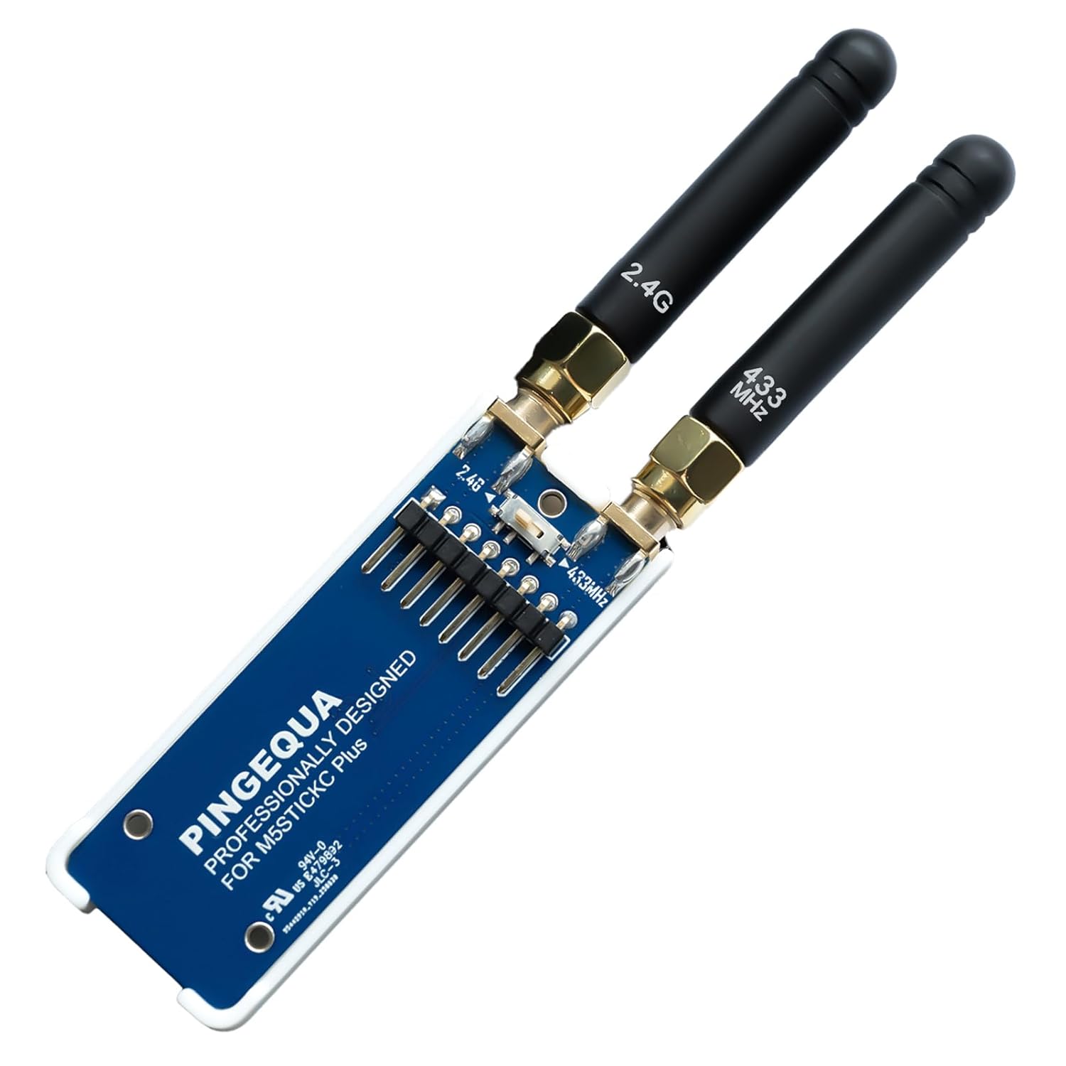
Image: The RF 2-in-1 module fully assembled with both 2.4GHz and 433MHz antennas attached, enclosed in its white protective case.

Resim: Yan view of the RF 2-in-1 module connected to the M5Stack StickC Plus, highlighting the antenna ports and the physical switch for selecting between 2.4GHz and 433MHz frequencies.
Kurulum Kılavuzu Videosu
Video: A step-by-step guide demonstrating the installation of the RF 2-in-1 Module onto the M5StickC Plus device.
4. Kullanım Talimatları
The RF 2-in-1 Module supports both NRF24 (2.4GHz) and CC1101 (433MHz) communication protocols. It is designed for use with Bruce firmware.
4.1. Selecting Communication Mode
The module features a physical switch to toggle between the 2.4GHz and 433MHz modes. Locate the small switch on the RF module board.
- Kullanmak için CC1101 (433MHz): Toggle the physical switch to the 433MHz position. Then, navigate to the RF-CONFIG menu in your Bruce firmware and select "RF MODULE -> CC1101 (legacy)".
- Kullanmak için NRF24 (2.4GHz): Toggle the physical switch to the 2.4GHz position. You can then utilize the NRF24 functions within the Bruce firmware.
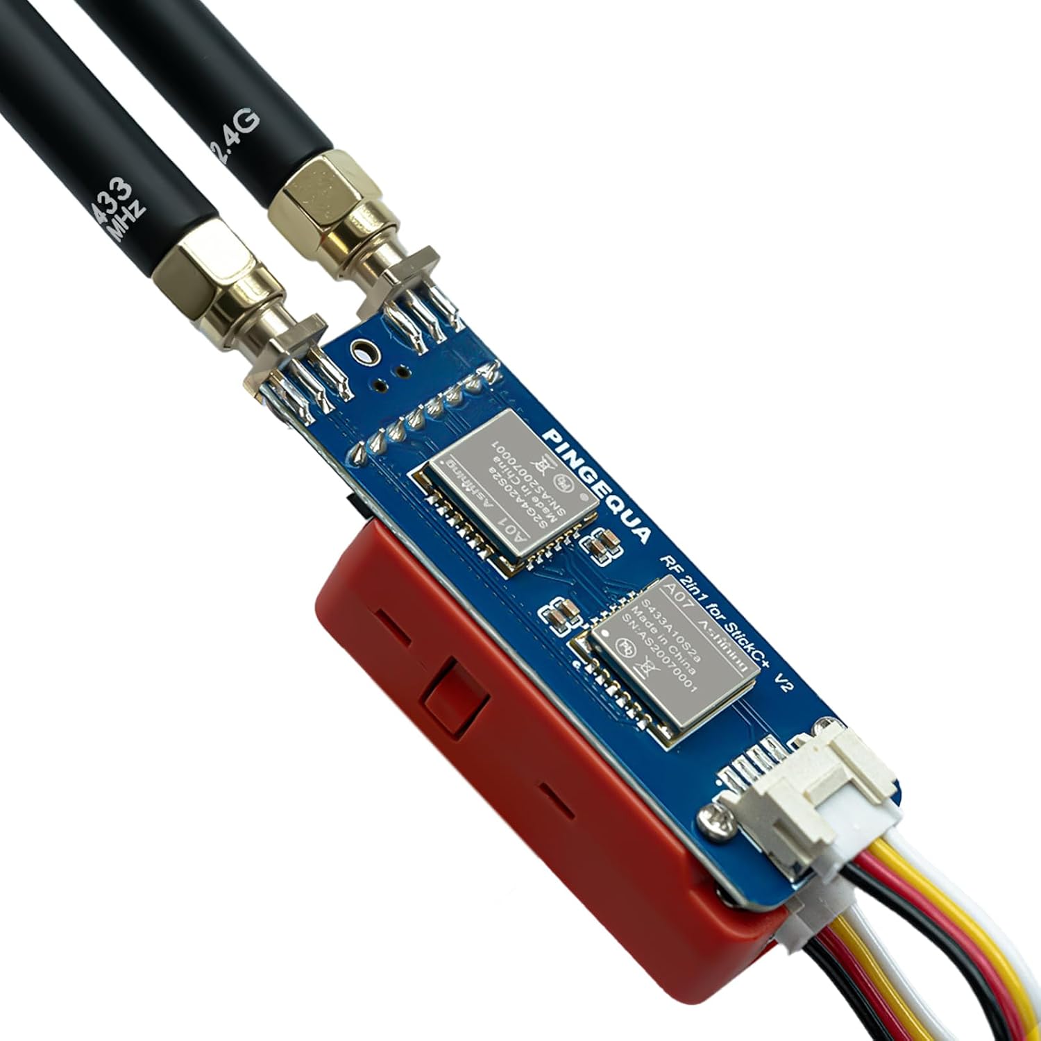
Resim: Üst view of the RF 2-in-1 module, highlighting the NRF24 and CC1101 chips, and the physical switch for selecting between 2.4GHz and 433MHz frequencies.
4.2. Bruce Firmware Compatibility
The module is fully compatible with Bruce firmware. For advanced configuration and help, refer to the official Bruce Wiki: https://github.com/pcbY/Bruce/wiki.
Not: Due to device power limits, 2.4 GHz anti-interference features, and legal regulations, the NRF24 effective range is limited. This module is designed for learning and research purposes only.
5. Sorun Giderme
5.1. "CC1101 Not Found" Error
If you encounter a "CC1101 not found" or "NRF24 not found" error, this is typically caused by SPI bus timing changes and power management settings in Bruce firmware versions v1.12 and v1.13, which prevent the M5StickC Plus from detecting the module.
Çözüm: To resolve this issue, you must flash the Latest Beta Version or v1.11 from the official Bruce web flasher. The Latest Beta includes critical patches for SPI initialization and AXP2101 power management, ensuring 100% module recognition and hardware stability.
Visit the Bruce Web Flasher at: https://bruce.computer/flasher
Firmware Fix Video
Video: This video demonstrates how to fix the "CC1101 / NRF24 Not Found" error on M5StickC Plus devices running Bruce Firmware v1.13 by flashing the correct beta firmware version.
6. Özellikler
| Paket Boyutları | 4.25 x 2.95 x 1.26 inç |
| Ürün Ağırlığı | 1.44 ons |
| Üretici | Pingequa |
| Ürün Model Numarası | RF 2-in-1 Module with Case |
| Bağlantı Teknolojisi | GPIO |
| İşletim Sistemi | ÜcretsizRTOS |

Image: Technical drawing showing the dimensions of the RF 2-in-1 module: 60.8mm (2.39 inches) in length and 22mm (0.86 inches) in width.
7. Garanti ve Destek
Garanti bilgileri ve teknik destek için lütfen üreticinin resmi web sitesine başvurun. webSite üzerinden satın alabilir veya müşteri hizmetleriyle iletişime geçebilirsiniz. Garanti talepleriniz için satın alma fişinizi saklayın.


