1. Ürün Bittiview
The SVBONY TransAir3 is a wireless HDMI transmitter and receiver system designed to extend 1080P@60Hz video signals up to 1000 feet (300 meters) in open areas. It features 9 auto-tuning 5.8GHz channels for stable connectivity, ultra-low latency of 0.06 seconds, and supports IR remote control. The receiver unit offers dual HDMI outputs for connecting two monitors, while the transmitter includes an HDMI loop-out port for local monitoring. This system is ideal for various applications including home entertainment, presentations, and video monitoring.

Image 1.1: SVBONY TransAir3 Wireless HDMI Extender system with its main features: 1080P 60fps, 1000FT Transmission Distance, 0.06s Low Latency, HDMI Loop Out & Dual HDMI Output, and IR Infrared Extension.
2. Paket İçeriği
Lütfen aşağıda listelenen tüm ürünlerin paketinizde mevcut olduğundan emin olun. Eksik veya hasarlı bir ürün varsa, lütfen müşteri hizmetleriyle iletişime geçin.
- Transmitter (TX) Unit x 1
- Receiver (RX) Unit x 1
- Antenler x 4
- Type-C to USB Cable x 2
- IR Cables x 2
- Mini High Definition Multimedia Interface Adapter x 1
- Micro High Definition Multimedia Interface Adapter x 1
- High Definition Multimedia Interface Cable x 2
- Kullanıcı Kılavuzu x 1
Video 2.1: An unboxing video demonstrating the contents of the SVBONY TransAir3 package, including the transmitter, receiver, cables, adapters, and user manual.

Image 2.2: A visual representation of the package contents, including the transmitter, receiver, antennas, various cables, and adapters.
3. Bileşen Tanımlaması
Familiarize yourself with the ports and controls on both the transmitter (TX) and receiver (RX) units.
3.1 Verici (TX) Ünitesi
- Anten Bağlantı Noktaları: For connecting the external antennas.
- Kızılötesi Arayüzü: For connecting the IR transmitter cable.
- Data Interface (HDMI Input): Connects to your source device (e.g., STB, PC, DVD).
- Data Interface (HDMI Loop Out): Connects to a local display for simultaneous monitoring.
- C Tipi Arayüz: Güç kaynağı için.
- M6 Threaded Interface: Aksesuarların montajı için.
- NP-F Battery Interface: For optional NP-F series battery power (battery not included).
- Güç düğmesi: Cihazı açmak/kapatmak için.
- Eşleştirme Düğmesi: Press and hold for 5 seconds to initiate pairing.
- LED ekran: Indicates battery status and signal connection.
3.2 Alıcı (RX) Ünitesi
- Anten Bağlantı Noktaları: For connecting the external antennas.
- Kızılötesi Arayüzü: For connecting the IR receiver cable.
- Data Interface (HDMI Output 1 & 2): Connects to display devices (e.g., TV, monitor).
- C Tipi Arayüz: Güç kaynağı için.
- M6 Threaded Interface: Aksesuarların montajı için.
- NP-F Battery Interface: For optional NP-F series battery power (battery not included).
- Güç düğmesi: Cihazı açmak/kapatmak için.
- Eşleştirme Düğmesi: Press and hold for 5 seconds to initiate pairing.
- LED ekran: Indicates battery status and signal connection.
Video 3.1: Detaylı bir inceleme view of the transmitter and receiver units, highlighting their various interfaces and ports for connection and power.

Resim 3.2: Yakın çekim view of the transmitter's side panel, detailing the Infrared Interface, Data Interfaces (HDMI In/Loop Out), and Type-C power port.

Resim 3.3: Yakın çekim view of the receiver's side panel, detailing the Infrared Interface, Data Interfaces (HDMI Outputs), and Type-C power port.

Image 3.4: Illustration of the M6 threaded interface for mounting and the NP-F battery interface for portable power options.

Image 3.5: Detail of the side panel showing the power switch and the pairing button (press and hold for 5 seconds).

Image 3.6: The LED display on the unit, which shows battery power status (solid blue for >20% or stable connection, blinking for <20% or signal loss).
4. Kurulum Talimatları
The TransAir3 system is designed for plug-and-play operation and is factory-paired for immediate use. Follow these steps for initial setup:
- Antenleri Bağlayın: Screw the four included antennas onto the antenna ports of both the transmitter (TX) and receiver (RX) units.
- Cihazlara güç verin: Connect the Type-C to USB cables to the Type-C interfaces on both the TX and RX units, then connect the USB ends to appropriate power sources (e.g., USB wall adapter, computer USB port). Alternatively, install optional NP-F series batteries (not included) into the battery interfaces.
- Connect Transmitter to Source: Connect an HDMI cable from your video source device (e.g., STB, PC, DVD player) to the HDMI Input port on the TX unit. If desired, connect a local display to the HDMI Loop Out port on the TX unit for simultaneous monitoring.
- Connect Receiver to Display: Connect an HDMI cable from the RX unit's HDMI Output port (or both HDMI Output ports for dual monitors) to your display device(s) (e.g., TV, monitor, projector).
- Güç Açık: Turn on both the TX and RX units using their respective power switches. The units should automatically connect.
- Bağlantıyı Doğrulayın: Check the LED display on both units. A solid blue light indicates a stable connection. If the light is blinking, refer to the troubleshooting section.

Image 4.1: A visual guide to the plug-and-play setup process: connecting the transmitter to a source, the receiver to a display, and confirming installation.
5. Kullanım Talimatları
5.1 Temel İşlemler
- Once connected and powered on, the TransAir3 system will automatically establish a wireless link.
- Ensure your display device is set to the correct HDMI input.
- The system automatically switches to the most stable 5.8GHz channel to maintain an uninterrupted connection.
5.2 IR Remote Control Functionality
The TransAir3 supports IR pass-through, allowing you to control your source device remotely from the display location.
- Connect the IR transmitter cable to the Infrared Interface on the TX unit and position the IR emitter near the IR receiver of your source device.
- Connect the IR receiver cable to the Infrared Interface on the RX unit and position the IR receiver in a location where it can receive signals from your remote control.
- Use your source device's original remote control (not included) to operate the device from the display location.
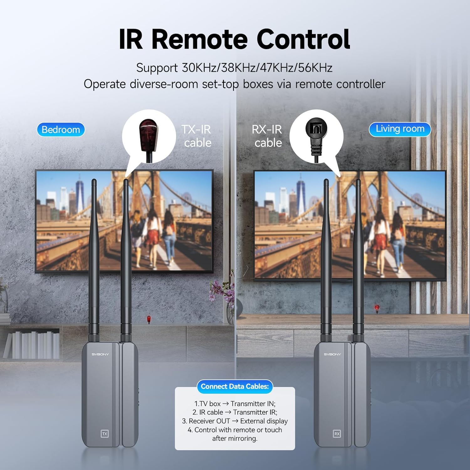
Image 5.1: Setup for IR remote control, showing the TX-IR cable connected to the source and the RX-IR cable positioned for remote signal reception.

Resim 5.2: Örn.ample of using the infrared remote control feature to manage a source device from a different room.
5.3 Dual Monitor Output (RX Unit)
The receiver unit is equipped with two HDMI output ports, allowing you to connect and display the same video signal on two separate monitors simultaneously.
- Connect HDMI cables from both HDMI Output ports on the RX unit to your two desired display devices.
- Both displays will show the same content from the source device.
5.4 Multiple Receiver Support (Optional)
One transmitter (TX) unit can be paired with up to four receiver (RX) units (additional RX units sold separately) to broadcast the signal to multiple displays.

Image 5.3: Illustration of a single transmitter broadcasting to multiple receiver units and their connected displays.
6. Bakım
To ensure the longevity and optimal performance of your SVBONY TransAir3 system, follow these maintenance guidelines:
- Temizlik: Use a soft, dry cloth to clean the exterior of the units. Avoid using liquid cleaners or aerosols, which may damage the components.
- Havalandırma: Ensure the units are placed in well-ventilated areas. Do not block the bottom air vents, as they are designed for heat dissipation.
- Depolamak: Uzun süre kullanılmadığı zamanlarda, cihazları serin, kuru ve doğrudan güneş ışığından ve aşırı sıcaklıklardan uzak bir yerde saklayın.
- Kablo yönetimi: Hasar görmesini önlemek için kabloları aşırı derecede bükmekten veya sıkıştırmaktan kaçının.

Image 6.1: The thermal design of the unit, highlighting the bottom air vents that facilitate heat dispersion for stable performance and extended service life.
7. Sorun Giderme
If you encounter issues with your TransAir3 system, refer to the following common problems and solutions:
| Sorun | Olası Neden | Çözüm |
|---|---|---|
| No video signal on display. |
|
|
| Video quality is poor or flickering. |
|
|
| IR uzaktan kumanda çalışmıyor. |
|
|
| LED display is blinking blue. |
|
|
8. Özellikler
Technical specifications for the SVBONY TransAir3 Wireless HDMI Extender.
| Özellik | Detay |
|---|---|
| Model Numarası | TransAir3 |
| Video Çözünürlüğü | 1080P@60Hz'e kadar |
| İletim Mesafesi | Açık alanlarda 300 metreye kadar (1000 fit). |
| Gecikme | 0.06 saniye |
| Kablosuz Frekans | 5.8GHz (9 auto-tuning channels) |
| Donanım Arayüzü | Radio Frequency, HDMI, Type-C, IR |
| Veri Bağlantı Protokolü | IEEE 802.11 |
| Güç Kaynağı | Type-C (external power supply) or NP-F batteries (not included) |
| Boyutlar (her birim için) | 2.5 x 1.18 x 4.56 inç (64 x 29 x 116 mm) |
| Ağırlık (birim başına) | Yaklaşık 0.9 lbs (0.41 kg) |
| Renk | Siyah + Gri |
| Özel Özellikler | HDMI Loop-Out, Dual HDMI Output, IR Remote Control, LED Status Display, Excellent Heat Dissipation |
9. Garanti ve Destek
SVBONY products are designed and manufactured to the highest quality standards. For warranty information, technical support, or service inquiries, please refer to the contact information provided in your product packaging or visit the official SVBONY webLütfen garanti talepleriniz için satın alma belgenizi saklayın.