
1. Giriş
This manual provides detailed instructions for the Coliao DC 6-30V Programmable Timer Relay Module. This versatile module is designed for various applications including smart home automation, industrial control, automatic irrigation systems, and ventilation control. It features an LED display for easy parameter setting and monitoring, and supports a wide operating voltage range with Micro USB 5V power supply option.

Resim 1.1: Üzeriview of two Coliao DC 6-30V Timer Relay Modules. Each module features a 3-digit LED display, control buttons, and screw terminals for connections.
2. Özellikler
- Çalışma Hacmitage: DC 6-30V (supports Micro USB 5V power supply)
- Çalışma Akımı: 50mA
- Statik Akım: 20mA
- Tetikleyici Kaynak: High trigger 3V-24V
- NO (Normally Open) Maximum Load: < AC 250V/10A, < DC 30V/10A
- Çalışma Sıcaklığı: -20~60℃
- Hizmet Ömrü: 100,000'dan fazla kez
- Zamanlama Aralığı: 0.1 seconds (min.) ~ 999 minutes (max.), continuously adjustable
- Boyutlar: Yaklaşık 6.4 x 3.8 x 1.7 cm (2.52 x 1.50 x 0.67 inç)
- Özellikler: Optocoupler isolation, enhanced anti-interference ability, industrial-grade circuit board, permanent parameter storage after power off, reverse polarity protection diode, emergency stop function.
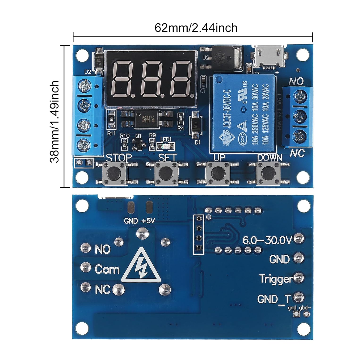
Resim 2.1: Üst ve alt views of the timer relay module, showing dimensions (62mm x 38mm) and key components like the LED display, control buttons (STOP, SET, UP, DOWN), Micro USB port, and terminal blocks.
3. Kurulum ve Kablolama
Proper wiring is crucial for the safe and correct operation of the timer relay module. Ensure all connections are secure before applying power.
3.1 Güç Kaynağı
- The module can be powered by a DC 6-30V source connected to the "Input (+)" and "GND (-)" terminals.
- Alternatively, a Micro USB 5V power supply can be used via the Micro USB port.
3.2 Trigger Signal
- The trigger signal (3V-24V) should be connected to the "Trigger Signal" terminal.
- The ground for the trigger signal can be connected to "GND_T(-)".

Image 3.1: Detailed connection diagram showing input power (DC 6-30V), trigger signal (3V-24V), Micro USB 5V power supply, and output relay connections (NO, COM, NC) for controlling a load. The four control buttons (STOP, SET, UP, DOWN) are also indicated.
3.3 Yük Bağlantısı
The relay output terminals are: NO (Normally Open), COM (Common), and NC (Normally Closed). Connect your load (e.g., a light bulb) according to your application's requirements.
- For a load that turns ON when the relay is active, connect it between NO and COM.
- For a load that turns OFF when the relay is active, connect it between NC and COM.
3.4 Common Ground Configuration
The two pins labeled "GND" and "GND_Trigger" can be short-circuited to establish a common ground for both the trigger signal and the main circuit, simplifying wiring in certain setups.

Image 3.2: Diagram illustrating how to short-circuit the "GND" and "GND_Trigger" pins to create a common ground for the trigger signal and the main power supply.
3.5 Kablolama Şemaları
Below are common wiring configurations for different applications:

Image 3.3: Two wiring diagrams. The top diagram shows "Weak Current Controlling Strong Current," where the module's power and trigger are separate from the AC load. The bottom diagram shows "Sharing One Power Supply," where the module and the DC load share the same power source.
4. Çalışma Modları
The module offers several programmable operation modes. Parameters OP (conduction time), CL (off time), and LOP (circuit times) can be set individually and are saved permanently after power off.
4.1 Mode P1: Single Trigger Delay
- Upon receiving a trigger signal, the relay turns ON for the set OP time, then turns OFF.
- P1.1: Re-triggering the signal during the OP period is ignored.
- P1.2: Re-triggering the signal during the OP period resets the timer (re-clocks).
- P1.3: Re-triggering the signal during the OP period disconnects the relay and stops timing.
- P1.4 (Random Mode): The relay conducts for the OP time only once when power is applied, without requiring an external trigger.
4.2 Mode P2: Delay Before Conduction
After receiving a trigger signal, the relay remains OFF for the set CL time, then turns ON for the set OP time. After the OP time, the relay turns OFF.
4.3 Mode P3.1: Cyclic Operation with Trigger Reset
Upon receiving a trigger signal, the relay turns ON for OP time, then turns OFF for CL time. This cycle repeats for LOP times. If a re-trigger signal is received within the timing cycle, the relay disconnects and stops timing.
4.4 Mode P3.2: Automatic Cyclic Operation
No trigger signal is required at power-on. The relay turns ON for OP time, then turns OFF for CL time. This cycle repeats for LOP times automatically.
4.5 Mode P4: Signal Retention
The timing resets upon receiving a trigger signal, and the relay contacts remain connected. When no signal is present, the relay turns OFF after the set OP time. If a signal is re-triggered during the OP timing period, the timing is reset.
5. Parameter Setting and Display
The module uses a 3-digit LED display to show current settings and timing. Use the "SET", "UP", and "DOWN" buttons to navigate and adjust parameters.
5.1 Setting Parameters (OP, CL, LOP)
- Basın AYARLAMAK button to enter parameter setting mode. The display will show the current mode (e.g., P1.1).
- Kullanın UP Ve AŞAĞI buttons to select the desired operation mode (P1.1 to P4).
- Basmak AYARLAMAK again to move to the next parameter (OP, CL, LOP, depending on the mode).
- Kullanmak UP Ve AŞAĞI to adjust the value of the parameter. A short press changes by 0.1, a long press changes rapidly.
- Basmak AYARLAMAK to confirm the value and move to the next parameter or exit setting mode.
- All parameters are saved automatically and permanently after setting.
5.2 Relay Using Mode (ON/OFF)
This setting determines if the relay is allowed to conduct during its ON time or if it remains always closed.
- AÇIK: Relay is allowed to conduct within the set OP time.
- KAPALI: Relay is banned from conducting and remains in a closed status (always off).
5.3 Uyku Modu
The module features two display modes to conserve power or maintain visibility.
- C-P (Sleeping Mode): If no operation occurs for 5 minutes, the digital display automatically turns off. The program continues to run in the background.
- O-d (Normal Mode): The digital display remains on continuously.
To switch between C-P and O-d modes, long press the DURMAK button for 2 seconds and then release. The current state will flash briefly before returning to the main interface.
6. Bakım
To ensure the longevity and reliable operation of your Coliao Timer Relay Module, follow these general maintenance guidelines:
- Temiz tut: Regularly clean the module with a soft, dry cloth to prevent dust accumulation, which can affect performance.
- Nemden Kaçının: Protect the module from water, humidity, and corrosive environments. Operate it within the specified working temperature range (-20~60℃).
- Güvenli Bağlantılar: Periodically check all wiring connections to ensure they are tight and free from corrosion. Loose connections can lead to intermittent operation or damage.
- Power Off Before Servicing: Always disconnect power to the module and any connected loads before performing any maintenance or wiring changes.
7. Sorun Giderme
If you encounter issues with your Coliao Timer Relay Module, refer to the following troubleshooting steps:
- Modül Açılmıyor:
- Güç kaynağı hacmini kontrol edintage (DC 6-30V or Micro USB 5V) to ensure it is within the specified range.
- Verify that the power connections to the module are correct and secure (positive to Input (+), negative to GND (-)).
- Relay Not Activating/Deactivating:
- Ensure the trigger signal is applied correctly (3V-24V to Trigger terminal).
- Check the selected operation mode (P1.x, P2, P3.x, P4) and its parameters (OP, CL, LOP) to ensure they match your intended behavior.
- Verify the load connections to the NO, COM, and NC terminals are correct.
- Confirm the "Relay Using Mode" is set to "ON" if you expect the relay to conduct.
- Parameters Not Saving:
- Bastığınızdan emin olun AYARLAMAK button to confirm each parameter change and exit the setting mode. Parameters are saved permanently after setting.
- Display Not Visible in C-P Mode:
- This is normal behavior for C-P (Sleeping Mode). The display turns off after 5 minutes of inactivity. The program continues to run.
- To reactivate the display, press any button or switch to O-d (Normal Mode) by long-pressing the DURMAK 2 saniye boyunca düğmeye basın.
- Modül Aşırı Isınması:
- Ensure the load connected to the relay does not exceed the maximum specified load (< AC 250V/10A, < DC 30V/10A).
- Verify proper ventilation around the module.
Bu adımları uyguladıktan sonra sorun devam ederse, lütfen müşteri desteğiyle iletişime geçin.
8. Garanti ve Destek
This product is manufactured by Coliao. For specific warranty information, please refer to the purchase documentation or contact your retailer. For technical support or inquiries, please reach out to Coliao customer service.