Walfront ADF4351
Walfront ADF4351 Signal Generator Module User Manual
Model: ADF4351 (WALFRONTdu5g42h8fx)
1. Giriş
This manual provides comprehensive instructions for the Walfront ADF4351 Signal Generator Module. The module is a versatile RF source development board featuring the ADF4351 frequency synthesizer, capable of generating signals from 35MHz to 4.4GHz. It is designed for various electronic development and testing applications.
2. Güvenlik Bilgileri
- Ensure proper power supply (DC4-9V, typical 5V) to avoid damage.
- Handle the module with care to prevent electrostatic discharge (ESD).
- Do not attempt to modify the circuit board unless you are a qualified professional.
- Cihazınızı nemden ve aşırı sıcaklıklardan uzak tutunuz.
3. Paket İçeriği
Paketin içinde tüm öğelerin mevcut olduğundan emin olun:
- 1 x ADF4351 Signal Generator Module
- 1 x SMA Holder (likely referring to the SMA connectors or an adapter)
- 1 x USB Kablosu
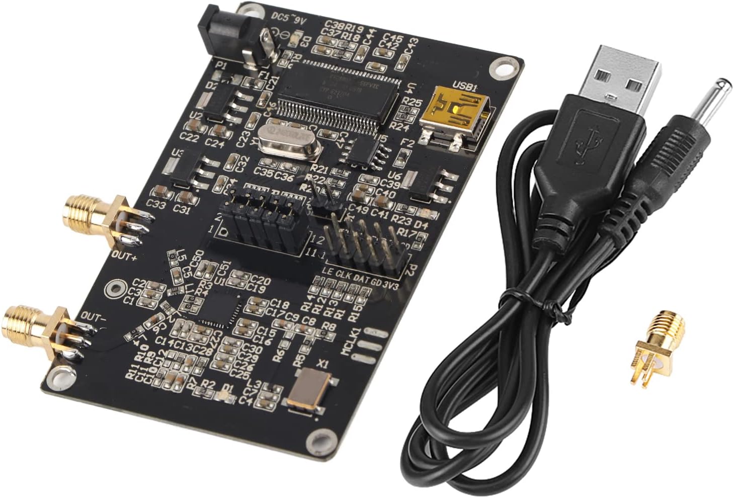
Figure 3.1: Contents of the Walfront ADF4351 Signal Generator Module package.
4. Ürün Bittiview
The Walfront ADF4351 module integrates a frequency synthesizer and voltage-controlled oscillator (VCO) to generate a wide range of RF frequencies. Key components and interfaces are detailed below.

Şekil 4.1: Üst view of the ADF4351 Signal Generator Module.

Şekil 4.2: Açısal view of the ADF4351 Signal Generator Module.
4.1 Temel Özellikler
- Output Frequency Range: 35MHz - 4.4GHz (ADF4351).
- Entegre Cilttage Controlled Oscillator (VCO) with a fundamental frequency range of 2200 MHz to 4400 MHz.
- Frequency division circuit (1/2/4/8/16) for lower frequencies.
- Control Interface: Three-wire SPI.
- Default crystal oscillator: +/-50ppm 25M active crystal.
- Mute function for RF output level control.
- Auxiliary RF output available.
4.2 Bileşen Tanımlama
- DC002 Interface (DC5-9V): Güç girişi bağlantı noktası.
- USB1: USB interface for connection to a computer.
- ÇIKIŞ+ / ÇIKIŞ-: SMA female connectors for RF signal output.
- P1, P2, P3: Control pin headers for SPI communication and status locking.
- ADF4351 IC: Main frequency synthesizer chip.
- Kristal Osilatör: Provides reference clock.
5. Kurulum
5.1 Güç Bağlantısı
- Connect the provided USB cable to the USB1 port on the module.
- Connect the other end of the USB cable to a computer or a 5V USB power adapter.
- Alternatively, connect a DC power supply (4-9V, typical 5V) to the DC002 interface. Ensure correct polarity.
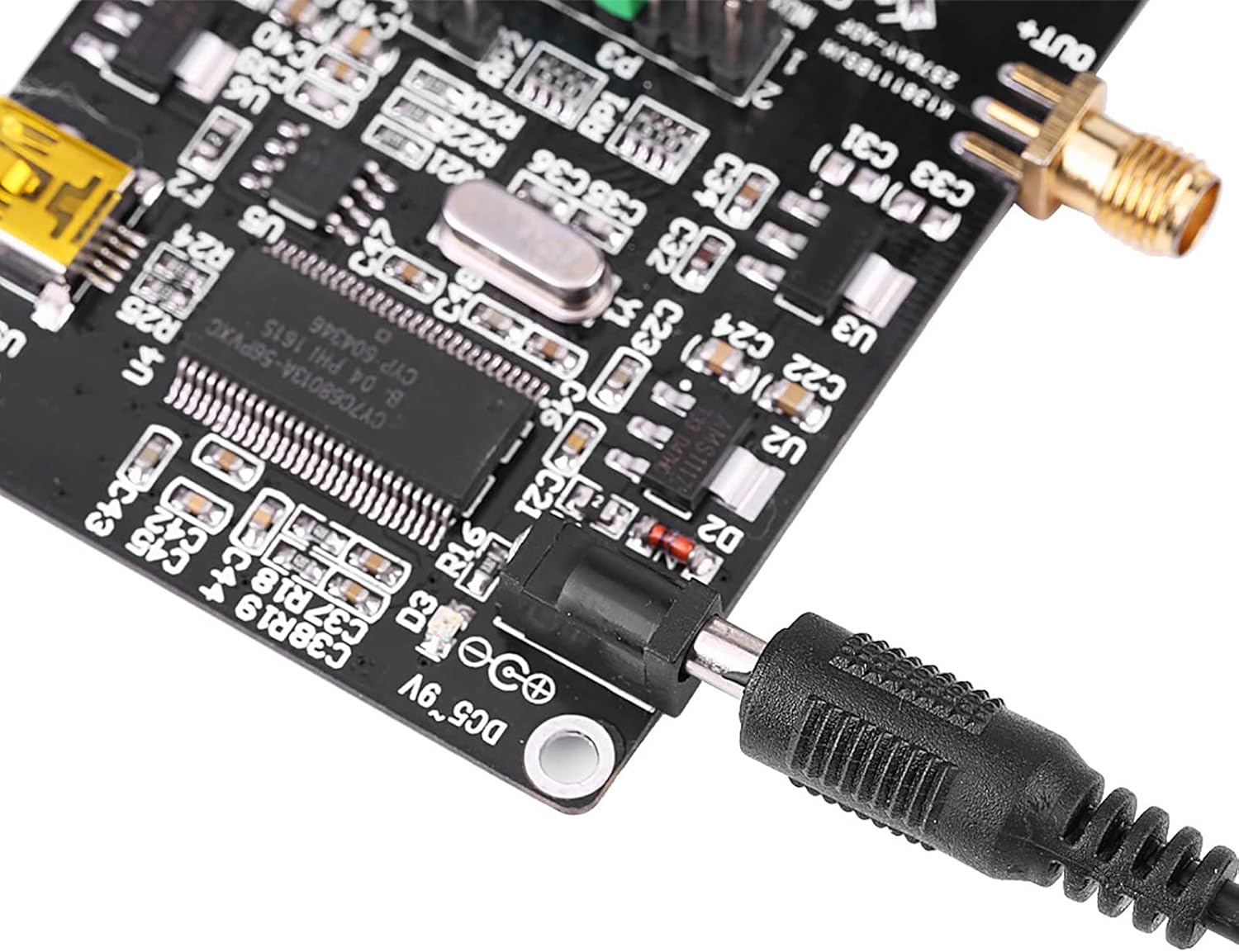
Figure 5.1: Connecting the DC power supply.
5.2 Bilgisayar Bağlantısı
The module can be controlled via a computer using the USB interface. Drivers may be required depending on your operating system. The manufacturer provides a PDF circuit diagram and STM32 test program for development.

Figure 5.2: USB port for computer connection.
6. Operasyon
6.1 Yazılım Kontrolü
The ADF4351 module is typically controlled using dedicated software on a computer. The manufacturer provides an official software interface for configuration. This software allows for setting various parameters including frequency, output power, and modulation.
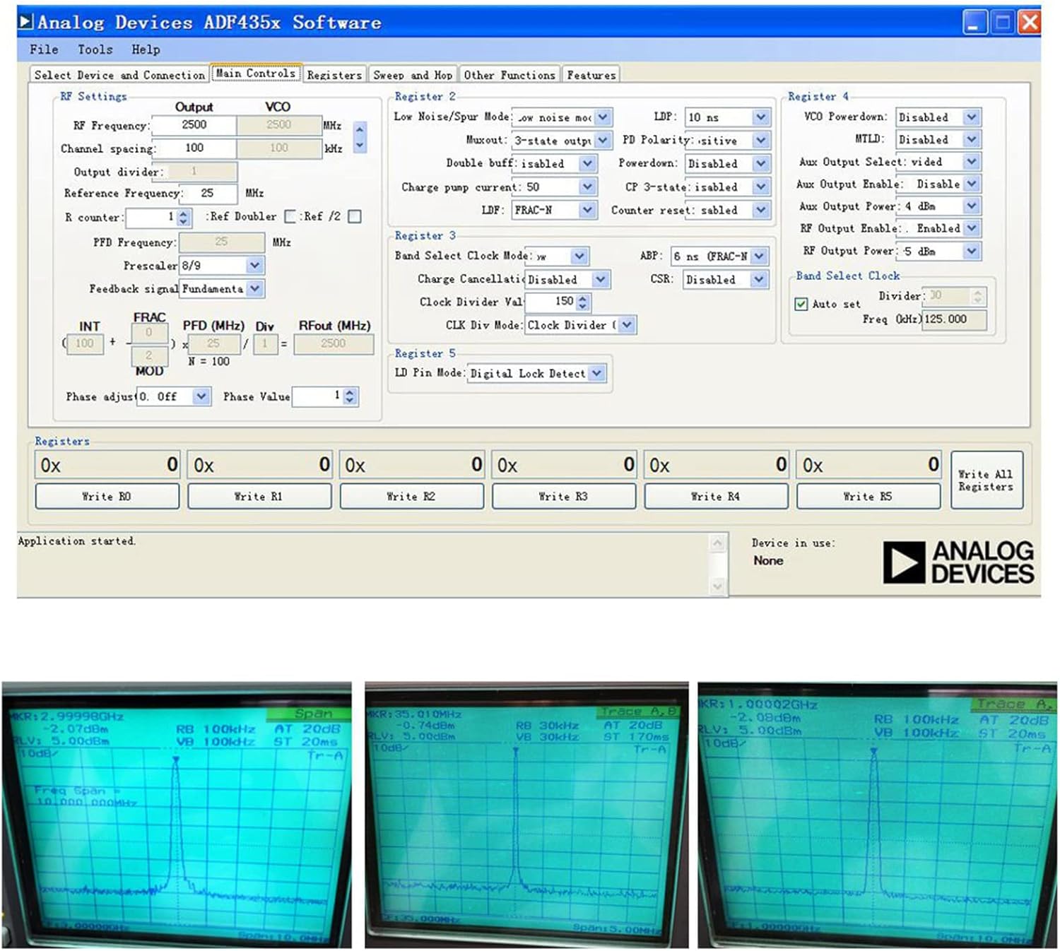
Figure 6.1: Analog Devices ADF435x Software interface for module control.
6.2 Frequency Generation
The module can generate frequencies from 35MHz to 4.4GHz. The output type varies with frequency:
- 2.2GHz - 4.4GHz: Fundamental (sine wave) output.
- 35MHz - 2.2GHz: Fundamental division (square wave) output.
The software allows for precise frequency setting, including point frequency, sweep, and frequency hopping. Stepping can be as fine as 1KHz, or 0.1KHz depending on the crystal frequency.

Şekil 6.2: Ör.ample frequency outputs displayed on an oscilloscope.
6.3 Sessize Alma İşlevi
For isolation applications, the RF output level can be muted. This function can be controlled either via a dedicated pin or through the software interface. The auxiliary RF output can also be turned off when not in use.
7. Özellikler
| Özellik | Şartname |
|---|---|
| Çıkış Frekans Aralığı | ADF4351: 35MHz - 4.4GHz |
| Güç Kaynağı | DC002 Interface DC4-9V (typical 5V) |
| Output Type (2.2-4.4GHz) | Fundamental (Sine Wave) |
| Output Type (35MHz-2.2GHz) | Fundamental Division (Square Wave) |
| Çıkış Konektörü | SMA Kadın |
| Kontrol Arayüzü | Three-wire SPI |
| Kristal Osilatör | +/-50ppm 25M Active Crystal |
| Ürün Ağırlığı | 1.38 ons (yaklaşık 39g) |
| Paket Boyutları | 3.94 x 2.76 x 0.79 inç (yaklaşık 10 x 7 x 2 cm) |
| Model Numarası | WALFRONTdu5g42h8fx |
8. Bakım
- Modülü temiz ve tozdan arındırılmış halde tutun. Temizlik için yumuşak, kuru bir bez kullanın.
- Modülü kullanılmadığı zamanlarda kuru ve serin bir ortamda saklayın.
- Avoid exposing the module to strong electromagnetic fields.
- Regularly check connections for secure fit.
9. Sorun Giderme
| Sorun | Olası Neden | Çözüm |
|---|---|---|
| Güç göstergesi yok | Yanlış güç kaynağı hacmitage or connection. | Verify power supply is 4-9V DC and connected correctly. Check USB cable connection. |
| RF çıkışı yok | Software not configured, mute function active, or incorrect frequency settings. | Ensure software is running and configured correctly. Check if the mute function is enabled. Verify frequency settings are within the module's range. |
| Module not recognized by computer | Eksik veya hatalı USB sürücüleri. | Install necessary USB drivers. Try a different USB port or cable. |
10. Garanti ve Destek
For warranty information and technical support, please refer to the documentation provided with your purchase or contact Walfront customer service. Circuit diagrams in PDF format and STM32 test programs are available for development purposes.
Ask a question about this manual
Ask about setup, troubleshooting, compatibility, parts, safety, or missing instructions. Manuals+ will review the question and use this page’s manual context to help answer it.