
1. Giriş
The UNI-T UT526 is a multifunction electrical installation tester designed for comprehensive electrical system analysis. It accurately measures insulation resistance, RCD (Residual Current Device) status, low resistance continuity, and AC/DC voltage. This device is suitable for testing power distribution systems, lightning protection systems, and wiring systems to ensure safe operation and compliance with electrical standards.

Şekil 1: Ön view of the UNI-T UT526 Multifunction Electrical Installation Tester.
2. Güvenlik Bilgileri
Before operating the UT526, read and understand all safety warnings and operating instructions. Failure to follow these instructions may result in electric shock, fire, or serious injury. Keep this manual for future reference.
- Kullanmadan önce cihazın iyi çalışma koşullarında olduğundan emin olun.
- Test cihazı hasarlı görünüyorsa veya test uçları hasar görmüşse kullanmayın.
- Verify the correct function of the tester on a known voltagKullanım öncesi ve sonrası kaynak.
- Adhere to all local and national safety codes.
- Uygun kişisel koruyucu ekipman (KKD) kullanın; bunlar arasında güvenlik gözlükleri ve yalıtımlı eldivenler de bulunur.
- Avoid working alone when performing electrical tests.
- Herhangi bir fonksiyon için maksimum giriş değerlerini aşmayın.
- Ensure the circuit under test is de-energized and locked out before making connections for resistance or continuity measurements.
3. Paket İçeriği
Carefully unpack the box and ensure all items listed below are present and undamaged. If any item is missing or damaged, contact your supplier immediately.
- 1 x UT526 Earth Resistance Tester
- 1 x Test Lead Set
- 1 x Alligator Clip Set
- 1 x İngilizce Kılavuzu
- 1 x Omuz Askısı
- 1 x Taşıma Çantası
- 1 x Renk Kutusu
Note: Batteries are not included and must be purchased separately (1.5V AA batteries x 6).
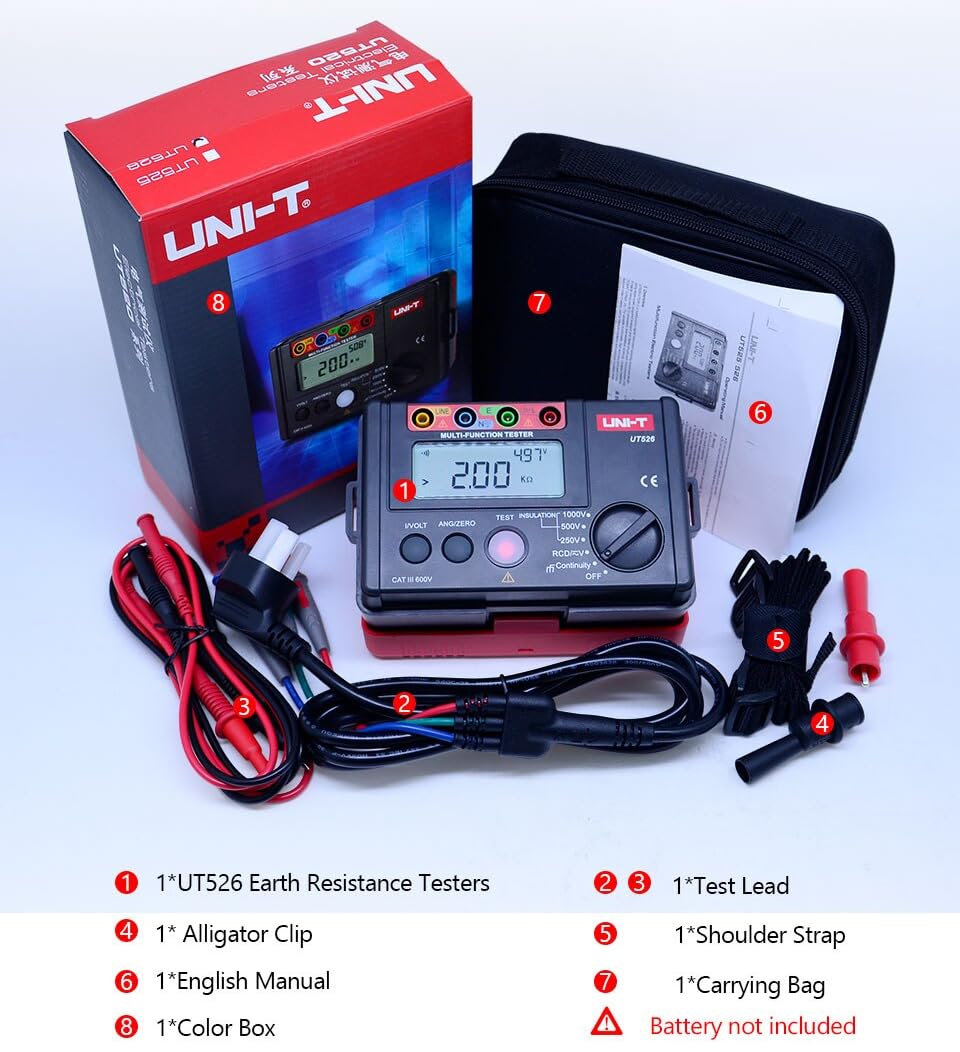
Figure 2: Included components of the UT526 package.
4. Ürün Özellikleri
The UNI-T UT526 offers a range of features for reliable electrical installation testing:
- Ekran Sayısı: 10000 for precise readings.
- Manuel Aralık: Allows for specific range selection.
- Phase Switch (RCD): Supports 0° and 180° phase testing.
- Düşük Pil Göstergesi: Pillerin değiştirilmesi gerektiğinde uyarı verir.
- Auto AC/DC VoltagKimlik: Simplifies voltage ölçümleri.
- Red Warning Lights: Visual alert for hazardous conditions.
- Sertifikalar: CE, UKCA compliant.
5. Kurulum
Before first use, install the batteries and prepare the test leads.
5.1 Pil Kurulumu
- Cihazın arka tarafında bulunan pil bölmesini bulun.
- Pil kapağını açmak için bir tornavida kullanın.
- Insert 6 x 1.5V AA batteries, observing the correct polarity.
- Pil kapağını yerine takın ve vidayla sabitleyin.
5.2 Test Uçlarının Bağlanması
Connect the test leads to the appropriate input terminals on the UT526. The terminals are color-coded and labeled for clarity (e.g., LINE, N, E, L).
6. Kullanım Talimatları
The UT526 offers various measurement functions. Select the desired function using the rotary switch.
6.1 Measuring Insulation Resistance
This function measures the insulation resistance of electrical circuits and equipment.
- Turn the rotary switch to one of the insulation test voltage settings: 100V, 250V, 500V, or 1000V.
- Insert test leads into the input terminals (Red to LINE, Black to N) and connect them to the circuit under test. High voltage, LINE terminalinden çıktıdır.
- For continuous measurement, press the TEST button. The tester will self-lock, output the test voltage, and emit a warning light simultaneously.
- Once the measurement is finished, press TEST again to unlock and stop the continuous measurement.
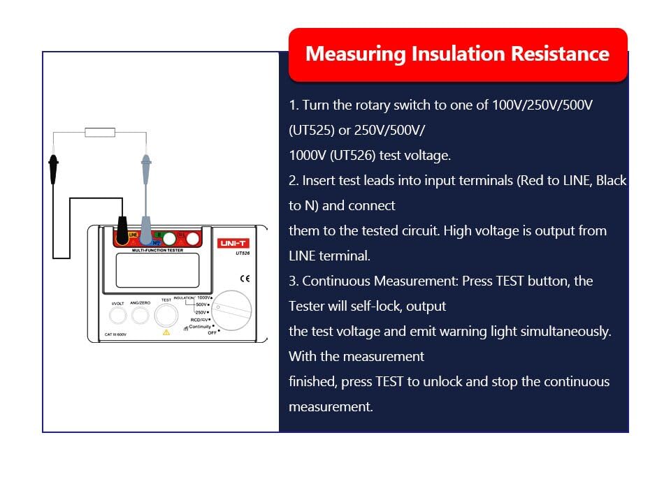
Figure 3: Setup for measuring insulation resistance.
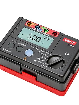
Figure 4: UT526 performing an insulation resistance test with warning light activated.
6.2 RCD Testi (Kaçak Akım Cihazı)
The RCD test function verifies the proper operation of Residual Current Devices, ensuring they trip within specified parameters.
- Turn the rotary switch to the RCD function.
- Connect the test leads to the appropriate terminals of the RCD or circuit.
- Select the desired test current and phase (0° or 180°) using the function buttons.
- Initiate the test. The device will measure the trip time and display the result.
Video 1: Demonstration of the RCD test function using the UNI-T UT526. This video shows the connection and operation of the RCD test, illustrating how the device measures the trip time of a residual current device.

Figure 5: UT526 connected for an RCD test.
6.3 Low Resistance Continuity Measurement
This function checks for continuity in circuits and measures low resistance values.
- Turn the rotary switch to the Continuity function.
- Connect the test leads across the component or circuit to be tested.
- The display will show the resistance value. An audible beep indicates continuity (typically below a certain resistance threshold).

Figure 6: UT526 performing a low resistance continuity test on a motor.
6.4 AC/DC Cilttage Ölçüm
The UT526 can measure both AC and DC voltagee.
- Döner anahtarı V (Ses Seviyesi) konumuna çevirin.tage) function. The device will automatically identify AC or DC voltage.
- Connect the test leads in parallel with the circuit or component where voltage ölçülmelidir.
- Ekranda ölçülen hacim gösterilecektir.tage değeri.
6.5 Ground Resistance Measurement
While the UT526 is primarily a multifunction electrical installation tester, it also supports ground resistance measurements.
- Turn the rotary switch to the appropriate ground resistance setting (if available, or use continuity for basic checks).
- Connect the test leads according to the specific ground resistance testing method (e.g., 3-pole or 4-pole method, if supported by the model).
- Initiate the measurement and read the ground resistance value from the display.

Figure 7: UT526 connected for ground resistance testing.
7. Bakım
Doğru bakım, UT526 test cihazınızın uzun ömürlü olmasını ve doğruluğunu sağlar.
- Temizlik: Cihazı reklamla silinamp Bez ve hafif deterjan kullanın. Aşındırıcı temizleyiciler veya çözücüler kullanmayın. Saklamadan önce cihazın kuru olduğundan emin olun.
- Pil Değişimi: Pil seviyesi düşük göstergesi göründüğünde pilleri hemen değiştirin. Cihaz uzun süre kullanılmayacaksa, sızıntıyı önlemek için pilleri çıkarın.
- Depolamak: Store the tester in a cool, dry place, away from direct sunlight and extreme temperatures. Use the provided carrying bag for protection.
- Kalibrasyon: For professional use, periodic calibration by an authorized service center is recommended to maintain measurement accuracy.
8. Sorun Giderme
UT526 cihazınızla ilgili sorunlarla karşılaşırsanız, aşağıdaki yaygın sorunlar ve çözümlerine bakın:
| Sorun | Olası Neden | Çözüm |
|---|---|---|
| Cihaz açılmıyor | Bitmiş veya yanlış takılmış piller | Pilleri doğru kutuplara yerleştirerek değiştirin. |
| Yanlış okumalar | Poor test lead connection, out of calibration, environmental interference | Ensure secure connections. Check against a known source. Consider professional calibration. |
| RCD test fails to trip | Faulty RCD, incorrect test parameters, wiring issue | Verify RCD functionality independently. Check test current and phase settings. Inspect circuit wiring. |
| Ekranda "OL" (Aşırı Yük) yazısı görünüyor. | Measurement exceeds selected range or device capability | Select a higher range or ensure the measurement is within the device's specifications. |
9. Özellikler
Detailed technical specifications for the UNI-T UT526 Multifunction Electrical Installation Tester are provided below.

Figure 8: Comprehensive specifications for the UT526.
| Şartname | Değer |
|---|---|
| Marka | BİRİM-T |
| Örnek | HY-UT526 |
| Güç Kaynağı | Battery Powered (6 x 1.5V AA) |
| Ürün Ağırlığı | 0.6 kilo |
| Ürün Boyutları | 6.5 x 4.33 x 4.72 inç |
| Şartname Karşılandı | CE, ISO 9001, RoHS, UKCA |
| Görüntüleme Sayısı | 10000 |
| Yalıtım Direnci Testi Cilttages | 100V, 250V, 500V, 1000V |
| RCD Phase Switch | 0° ve 180° |
| Düşük Pil Göstergesi | Evet |
| Auto AC/DC Voltage Kimlik | Evet |
| Kırmızı Uyarı Işıkları | Evet |
10. Garanti
The UNI-T UT526 Multifunction Electrical Installation Tester comes with a 1 yıllık garanti from the date of purchase. This warranty covers defects in materials and workmanship under normal use. It does not cover damage caused by misuse, accident, unauthorized modification, or neglect. Please retain your proof of purchase for warranty claims.
11. Destek
For technical assistance, troubleshooting beyond this manual, or warranty inquiries, please contact UNI-T customer support. Refer to the official UNI-T webEn güncel iletişim bilgileri için lütfen sitenizi veya ürün ambalajınızı ziyaret edin.
UNI-T Yetkilisi Webalan: www.uni-trend.com