giriiş
This manual provides detailed instructions for the setup, operation, and maintenance of the Akozon ADF4351 Development Board. This board functions as a 35MHz to 4.4GHz RF source frequency synthesizer, designed for various applications requiring precise signal generation. Please read this manual thoroughly before using the device to ensure proper functionality and safety.
Ürün Bittiview
The ADF4351 Development Board is a versatile RF signal source. It features a well-designed circuit board layout for optimal performance and can be controlled via dedicated software on a computer. All control pins are accessible for flexible operation, supporting functions like frequency sweep and hopping.
- Well-Designed Circuit Board Layout: Ensures optimal performance and reliable operation for RF signal applications.
- Kullanışlı Kontrol Seçenekleri: Can be controlled by official software on an upper computer, with all control pins leaded out for easy access.
- Reliable Crystal Oscillator: Includes a default ±50ppm 25M active crystal oscillator for accurate and stable frequency synthesis.
- Flexible Control and Functionality: Features a three-wire SPI interface for pin and state locking, enabling point frequency sweep and frequency hopping with stepping options down to 1K (or 0.1K for low frequencies).
- Single-Chip Microcontroller Control: Equipped with a control interface for single-chip microcontrollers and compatible with ADF5355.
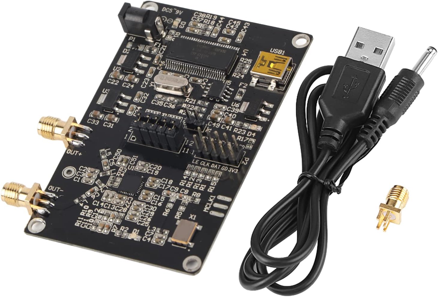
Şekil 1: The Akozon ADF4351 Development Board, shown with its included USB cable and an SMA connector. This image provides a general view Ürün ve aksesuarlarıyla ilgili.
Paket İçeriği
Aşağıda listelenen tüm öğelerin paketinizde mevcut olduğundan emin olun:
- 1 x ADF4351 Signal Generator Development Board
- 1 x SMA Holder
- 1 x USB Kablosu

Şekil 2: The USB cable supplied with the development board, used for power and data connection.
Kurulum Talimatları
- Güç Bağlantısı: Connect the provided USB cable to the USB1 port on the development board. The other end of the USB cable should be connected to a DC4-9V power source (typical 5V). Alternatively, a DC power adapter can be connected to the DC002 interface.
- Çıkış Bağlantısı: Connect your RF measurement equipment or application circuit to the SMA female connectors labeled "OUT+" and "OUT-".
- Yazılım Kurulumu: Download and install the official control software for the ADF4351 from the manufacturer's website or the provided download link: http://pan.baidu.com/s/1dE84sGp (password: nlwq).
- Sürücü Kurulumu: Ensure any necessary USB drivers for the board are installed on your computer. These are typically included with the control software or available from the manufacturer.
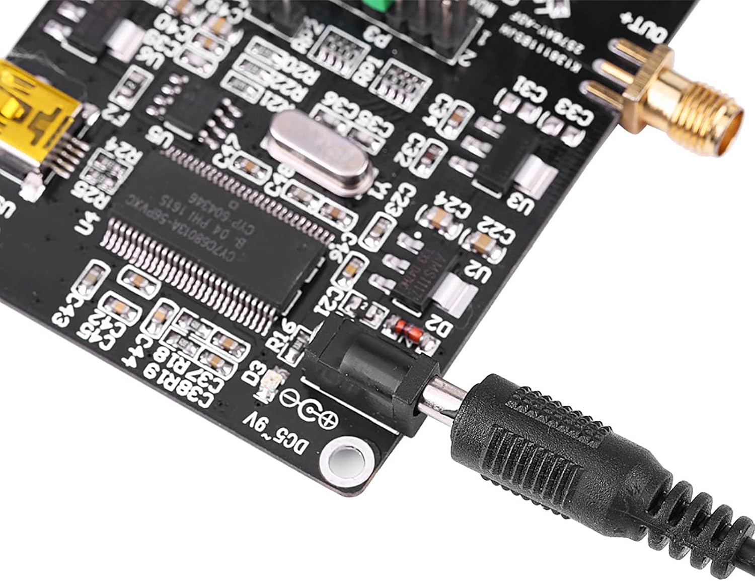
Şekil 3: Detail of the DC002 power input interface (DC5~9V) on the board.
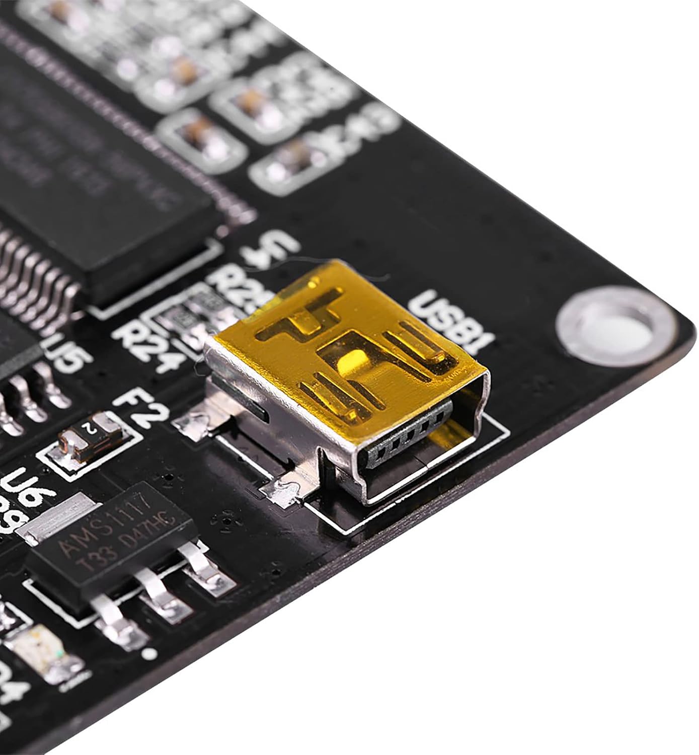
Şekil 4: Detail of the USB1 port for power and data connection.
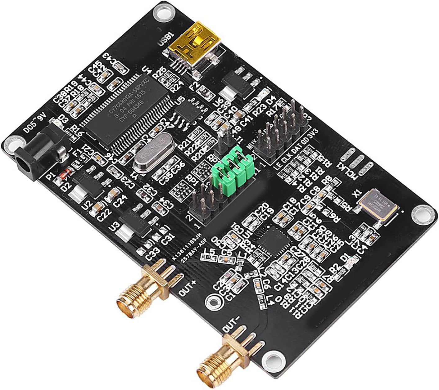
Şekil 5: Tepe view of the board highlighting the "OUT+" and "OUT-" SMA female connectors for signal output.
Kullanım Talimatları
- Launch Control Software: Open the installed ADF4351 control software on your computer.
- Cihaza Bağlan: Within the software, establish a connection to the ADF4351 Development Board. The software should detect the board automatically if drivers are correctly installed.
- Frekansı Ayarla: Use the software interface to set the desired output frequency. The ADF4351 supports an output frequency range of 35MHz to 4.4GHz.
- Configure Output: Adjust other parameters such as output power, modulation (if supported by software), and enable/disable the output signal.
- Advanced Control (SPI): For advanced users, the three-wire SPI control pins (LE, CLK, DAT, GD, 3V3) are exposed for direct microcontroller control. This allows for custom programming of functions like point frequency sweep and frequency hopping. The board is also compatible with ADF5355 control.

Şekil 6: Ayrıntılı view of the ADF4351 Development Board, indicating various components and control pin headers (P2, P3) for advanced interfacing.
Bakım
- Temizlik: Keep the board clean and free from dust. Use a soft, dry cloth for cleaning. Avoid using liquids or abrasive cleaners.
- Depolamak: Store the development board in a dry, static-free environment when not in use.
- İşleme: Handle the board by its edges to avoid touching sensitive components, especially to prevent electrostatic discharge.
Sorun giderme
- Güç Yok:
- Ensure the USB cable is securely connected to both the board and the power source.
- Verify the power source is providing 4-9V DC.
- Check for any visible damage to the power input port or cable.
- Software Not Detecting Board:
- Confirm that the USB cable is properly connected to the computer.
- Reinstall the control software and any associated drivers.
- Bilgisayarınızda farklı bir USB bağlantı noktası deneyin.
- No RF Output:
- Verify that the output frequency is set within the operational range (35MHz-4.4GHz).
- Check that the output is enabled in the control software.
- Ensure SMA connectors are securely attached to the "OUT+" and "OUT-" ports.
Özellikler
| Özellik | Şartname |
|---|---|
| Çıkış Frekans Aralığı | ADF4351: 35MHz - 4.4GHz |
| Güç Kaynağı | DC002 Interface DC4-9V (typical 5V) |
| Output Signal (2.2-4.4G) | Fundamental wave (sine wave) |
| Output Signal (35M-2.2G) | Fundamental division (square wave) |
| Sinyal Çıkış Konnektörü | SMA dişi |
| Kristal Osilatör | ±50ppm 25M active crystal oscillator |
| Kontrol Arayüzü | Three-wire SPI (LE, CLK, DAT, GD, 3V3) |
| Uyumluluk | ADF5355 (via control interface) |
| Ürün Ağırlığı | 36 gr (1.38 ons) |
| Ürün Boyutları | 3.94 x 2.76 x 0.79 inç |
Garanti ve Destek
For warranty information and technical support, please refer to the official Akozon website or contact your retailer. Additional resources, including circuit diagrams in PDF format and STM32 test programs, are available via the provided download link: http://pan.baidu.com/s/1dE84sGp (password: nlwq).


