giriiş
This manual provides essential information for the proper use and understanding of your CHANZON 5mm Red & Green LED Diode Lights. These bi-color LEDs are designed for various electronic projects, offering both red and green light emission from a single component. Please read this manual thoroughly before use.
Ürün Özellikleri
| Şartname | Değer |
|---|---|
| Miktar | 100 pieces / Packs |
| Lens Türü | 5mm Diameter / Transparent / Round |
| Emitting Colour (Red) | 620nm-625nm |
| Emitting Colour (Green) | 515nm-520nm |
| Luminous Intensity (Red) | 2000-3000mcd (Ultrabright) |
| Luminous Intensity (Green) | 15000-18000mcd (Ultrabright) |
| ViewAçı | 30 Derece |
| İleri Hacimtage (Kırmızı) | 2V-2.2V |
| İleri Hacimtage (Yeşil) | 3V-3.2V |
| Forward Current | 20mA |
| Netage | 0.1W |
| Lead Lengths | 29.5mm / 26.5mm / 28.5mm |
| Polarite | Common Anode (Longer Part) | 2 Cathode (Shorter Part) |
| Ortalama Hayat | 50000 Saat |
| Ürün Ağırlığı | 1.69 ons (48 Gram) |
| Ürün Boyutları | 7.09 x 5.91 x 0.71 inç |
Understanding Common Anode Bi-Color LEDs
These LEDs are Common Anode (CA) type. This means the longest lead is the common positive (+) terminal. The two shorter leads are the cathodes (-) for the red and green LEDs respectively.
- Longest Lead: Common Anode (+)
- Shorter Lead 1: Cathode (-) for Red LED
- Shorter Lead 2: Cathode (-) for Green LED
To illuminate the red LED, connect the common anode to a positive voltage source (e.g., +5V) and the red cathode to ground, typically through a current-limiting resistor. Similarly, for the green LED, connect the common anode to positive and the green cathode to ground via a resistor.

Figure 1: LED Dimensions and Polarity Diagram. This image illustrates the physical dimensions of the 5mm bi-color LED and clearly labels the common anode (longest lead) and the two cathode leads for red and green.
Kurulum ve Bağlantı
Proper setup is crucial for the longevity and performance of your LEDs. Always use a current-limiting resistor in series with each LED to prevent damage from excessive current.
Calculating Resistor Value:
Use Ohm's Law: R = (Vs - Vf) / I
- R: Resistor value in Ohms (Ω)
- Vs: Tedarik hacmitage (e.g., 5V from Arduino)
- Vf: ileri sestage of the LED (Red: 2V-2.2V, Green: 3V-3.2V)
- I: Desired forward current (typically 20mA or 0.02A for these LEDs)
Example for Red LED (Vs=5V, Vf=2.1V, I=0.02A): R = (5V - 2.1V) / 0.02A = 2.9V / 0.02A = 145 Ω. A common resistor value like 150 Ω or 220 Ω would be suitable.
Example for Green LED (Vs=5V, Vf=3.1V, I=0.02A): R = (5V - 3.1V) / 0.02A = 1.9V / 0.02A = 95 Ω. A common resistor value like 100 Ω or 120 Ω would be suitable.
Bağlantı Adımları:
- Identify the common anode (longest lead) and the two cathode leads.
- Connect the common anode lead to your positive voltage tedarik.
- Connect a calculated current-limiting resistor in series with each of the two cathode leads.
- Connect the other end of each resistor to the control pin (e.g., microcontroller output) or directly to ground if always on.
- Gücü vermeden önce tüm bağlantıların güvenli ve doğru olduğundan emin olun.
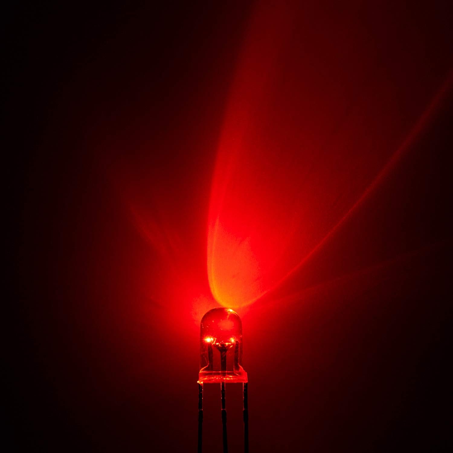
Figure 2: Packaging and Individual LED. This image displays the bulk packaging of 100 LEDs, alongside a single LED and examples of the red and green light output.
Operating the LEDs
These bi-color LEDs allow for individual control of red and green light, or a combination to create a mixed color (e.g., orange/yellow depending on intensity).
- Kırmızı ışık: Uygun hacmi uygulayıntage to the common anode and connect the red cathode (shorter lead) to ground via its resistor.
- Yeşil ışık: Uygun hacmi uygulayıntage to the common anode and connect the green cathode (shorter lead) to ground via its resistor.
- Mixed Color: Uygun hacmi uygulayıntage to the common anode and connect both red and green cathodes to ground via their respective resistors. The resulting color will be a blend of red and green.
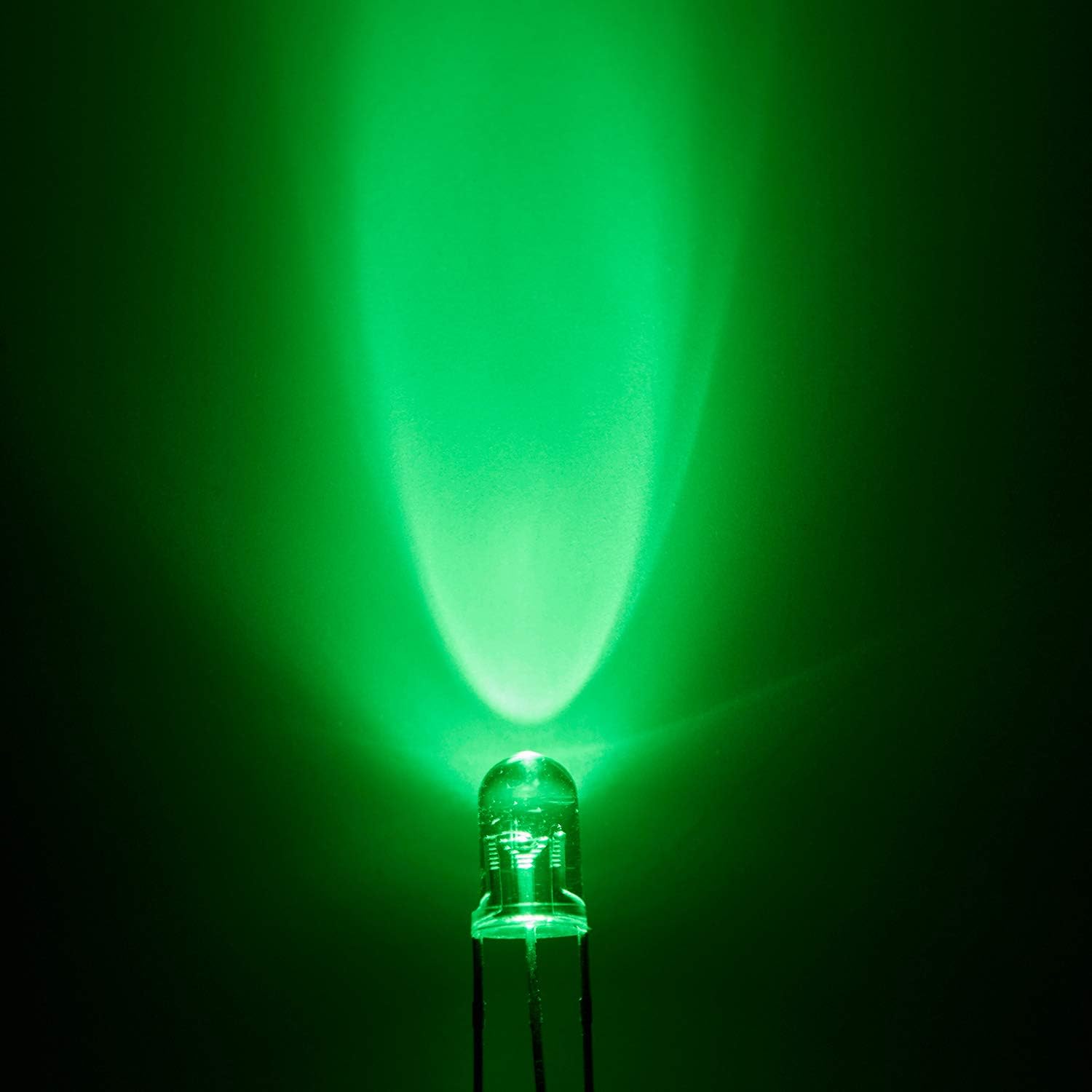
Figure 3: Red Light Emission. This image shows a single LED illuminated with red light, demonstrating its brightness and beam pattern.

Figure 4: Green Light Emission. This image shows a single LED illuminated with green light, demonstrating its brightness and beam pattern.
Bakım
These LEDs are robust electronic components and require minimal maintenance.
- Depolamak: Store LEDs in a dry, cool environment, preferably in their original anti-static packaging, to prevent damage from moisture or static discharge.
- İşleme: Avoid bending the leads excessively or repeatedly, as this can cause them to break. Handle by the body of the LED whenever possible.
- Temizlik: If necessary, gently wipe the LED lens with a soft, dry cloth. Avoid using harsh chemicals.
Sorun giderme
| Sorun | Olası Neden | Çözüm |
|---|---|---|
| LED yanmıyor. | Incorrect polarity, insufficient voltage, no current-limiting resistor, faulty connection, or damaged LED. | Verify common anode and cathode connections. Check power supply voltage. Ensure a resistor is in series. Inspect solder joints/connections. Test with a known good LED. |
| LED is too dim or too bright. | Incorrect resistor value. | Recalculate and replace the current-limiting resistor with the appropriate value for desired brightness. |
| Only one color lights up. | Connection issue with one of the cathode leads or its resistor. | Check the connection and resistor for the non-lighting color. Ensure the correct cathode is being driven. |
Ürün Videosu
Video 1: CHANZON LED Diode Light OverviewBu video, görsel bir özet sunmaktadır.view of various CHANZON LED diode lights, including 3mm and 5mm sizes, demonstrating both clear transparent and diffused lens types, and showing them in use on a breadboard.
Garanti ve Destek
For warranty information or technical support, please refer to the seller's policies on the purchase platform or contact CHANZON directly through their official channels. Keep your purchase receipt for any warranty claims.
You can visit the official CHANZON store for more products and support: CHANZON Store


