giriiş
The System Sensor HR-LF is a low frequency sounder designed for indoor use in security and surveillance systems, specifically for sound detection and alarm output. This device is engineered to provide clear and effective audible alerts, crucial for life safety applications. This manual provides essential information for the proper installation, operation, and maintenance of your HR-LF sounder.
Güvenlik Bilgileri
Please read and understand all instructions before installing or operating the HR-LF sounder. Failure to follow these instructions may result in property damage, injury, or death. This device must be installed by qualified personnel in accordance with all local and national electrical and fire codes.
- Gücü Kesin: Cihazı takmadan, bakımını yapmadan veya çıkarmadan önce daima devrenin elektriğini kesin.
- Uygun Kablolama: Ensure all wiring connections are secure and comply with the wiring diagram provided with the device.
- Çevresel Koşullar: Install the device in an environment that meets its specified operating conditions.
- Test: Regularly test the device after installation and during routine maintenance to ensure proper operation.
Paket İçeriği
Kuruluma başlamadan önce tüm öğelerin mevcut olduğundan emin olun:
- System Sensor HR-LF Low Frequency Sounder (Red)
- Montaj Donanımı (vidalar, dübeller)
- Kurulum Kılavuzu (bu belge)
Kurulum ve Yükleme
The HR-LF sounder is designed for surface mount installation. Follow these steps for proper setup:
- Konum seç: Select an indoor location that provides optimal sound coverage and complies with local codes. Ensure the mounting surface is flat and secure.
- Kablolamayı Hazırlayın: Route the necessary electrical wiring to the chosen mounting location. Ensure power is disconnected before proceeding.
- Montaj:
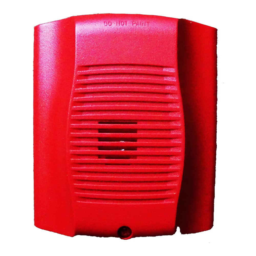
Resim: Ön view of the System Sensor HR-LF low frequency sounder. This red device features a grille for sound emission and mounting points for surface installation.
- Position the sounder base against the wall or ceiling at the desired mounting point.
- Mark the locations for the mounting screws.
- Gerekirse pilot delikler açın ve alçıpan montajında duvar dübellerini yerleştirin.
- Secure the sounder base to the mounting surface using the provided screws.
- Kablo Bağlantıları: Connect the field wiring to the terminal block on the sounder base according to the wiring diagram provided with the device. Pay close attention to polarity.
- Attach Sounder Head: Once wiring is complete and secure, attach the sounder head to the mounted base, ensuring it locks into place.
- Gücü Geri Yükle: After verifying all connections, restore power to the circuit.
- Test İşlemi: Perform an operational test as described in the "Operating Instructions" section.
Kullanım Talimatları
The System Sensor HR-LF low frequency sounder operates as an alarm output device, typically activated by a connected fire alarm control panel or security system. It is designed to produce a distinct low-frequency tone for occupant notification.
- Etkinleştirme: The sounder will activate when it receives a signal from the connected control panel, indicating an alarm condition.
- Sound Pattern: The HR-LF typically produces a temporal 3 pattern (three short pulses followed by a pause), which is standard for fire alarm notification. Refer to your control panel's documentation for specific output patterns.
- Devre dışı bırakma: The sounder will deactivate when the alarm condition on the control panel is cleared or reset.
Note: The HR-LF is an output device and does not have user-configurable settings directly on the unit. All operational parameters are controlled by the connected fire alarm or security system.
Bakım
Regular maintenance ensures the continued reliable operation of your HR-LF sounder.
- Temizlik: Periodically clean the exterior of the sounder with a soft, dry cloth to remove dust and debris. Do not use abrasive cleaners or solvents.
- Test: Conduct periodic functional tests in accordance with local codes and manufacturer recommendations (typically annually) to ensure the sounder activates and produces the correct sound pattern.
- Denetleme: Visually inspect the device for any signs of damage, loose connections, or obstructions to the sound output.
Sorun giderme
If your HR-LF sounder is not functioning as expected, refer to the following common issues and solutions:
| Sorun | Olası Neden | Çözüm |
|---|---|---|
| Sounder does not activate. | Cihaza güç gelmiyor. Yanlış kablolama. Control panel not sending activation signal. | Güç kaynağını doğrulayın. Check wiring connections against diagram. Inspect control panel status and output. |
| Sounder activates intermittently. | Gevşek kablo bağlantısı. Faulty control panel output. | Tüm kablo bağlantılarını sabitleyin. Consult control panel manual or contact qualified technician. |
| Ses zayıf veya bozuk. | Obstruction in front of sounder. Cihaz hasarı. | Herhangi bir engeli kaldırın. Fiziksel hasar olup olmadığını kontrol edin; gerekirse değiştirin. |
If troubleshooting steps do not resolve the issue, contact System Sensor technical support or a qualified service technician.
Özellikler
| Marka | Sistem Sensörü |
| Model Numarası | HR-LF |
| Malzeme | Plastik |
| Stil | Modern |
| Montaj Tipi | Yüzey Montajı |
| Çıktı Türü | Alarm |
| Belirli Kullanımlar | Indoor, Sound Detection |
| ASIN | B015NEAOB2 |
| İlk Mevcut Tarih | 5 Ekim 2016 |
Garanti ve Destek
System Sensor products are designed for reliability and performance. For specific warranty information, please refer to the warranty statement included with your product packaging or visit the official System Sensor website. For technical support, installation assistance, or service inquiries, please contact System Sensor customer service or your authorized distributor.
İletişim bilgileri genellikle üreticinin web sitesinde bulunabilir. website veya ürün ambalajı.


